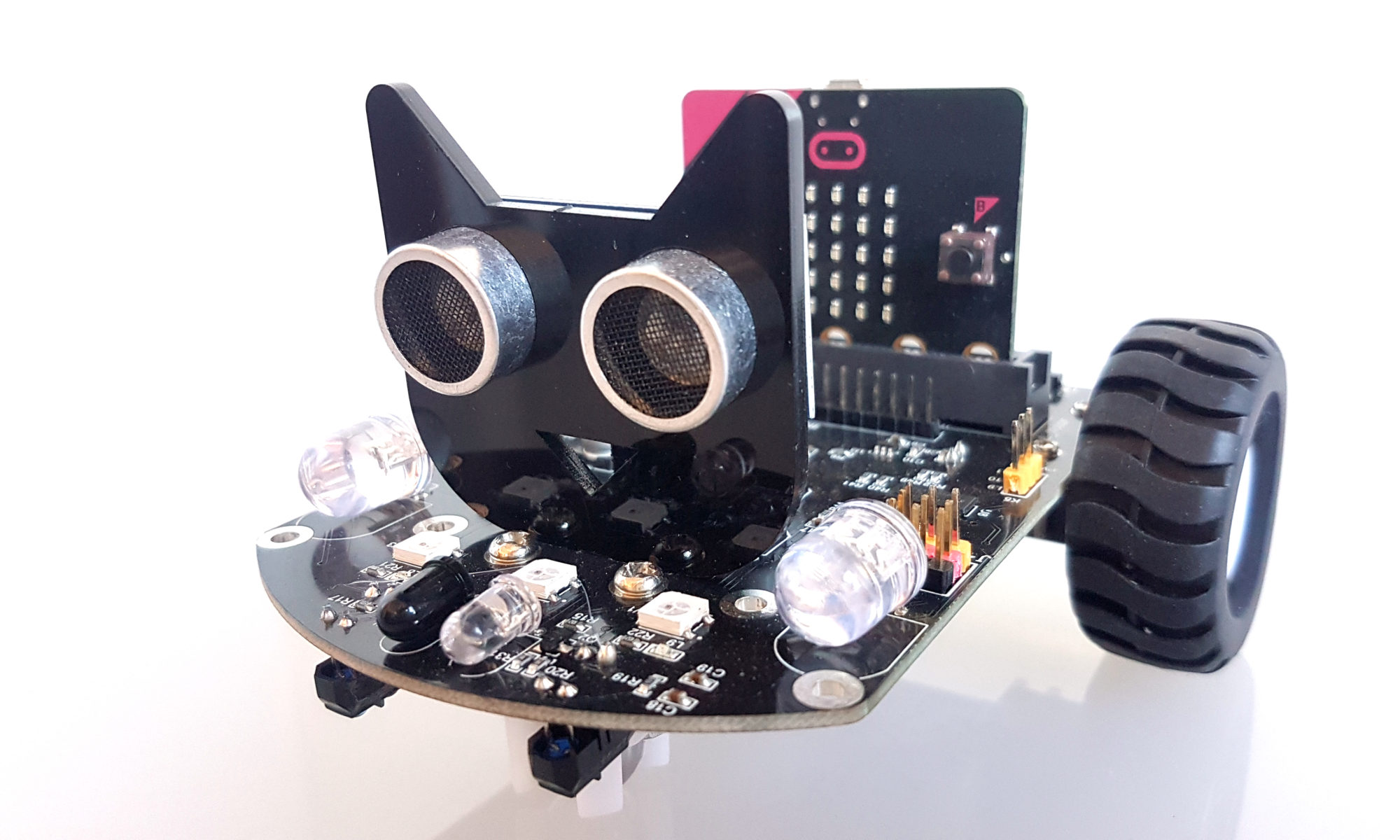
Micro:bit admite varios lenguajes de programación y uno de ellos es Phyton. Os mostramos algunos ejemplo para que os ayuden a familiarizaros con este lenguaje de programación.
HOLA MUNDO
OBJETIVO: Mostrar un texto en la placa micro:bit
CÓDIGO:
from microbit import *
while True:
    display.scroll('Hola Microlog')
    sleep(2000)
DIBUJA UN CORAZÓN
OBJETIVO: Mostrar en la placa micro:bit el dibujo de un corazón
CÓDIGO:
from microbit import *
while True:
    display.show(Image.HEART)
    sleep(2000)
DIBUJA UNA IMAGEN PERSONALIZADA
OBJETIVO: Mostrar en la placa micro:bit un dibujo diseñado por nosotros. Utilizamos la instrucción Image. A esta instrucción le introducimos como parámetros 5 códigos. Cada código representa una fila de leds de la matriz. Cada uno de estos 5 códigos contiene 5 dígitos que representan cada led de una fila de la matriz. Si introducimos el dígito 9, indicamos que ese led estará encendido. Si introducimos el dígito 0, el led estará apagado.
CÓDIGO:
from microbit import *

boat = Image("09090:09090:09090:99999:09990")

display.show(boat)
ANIMACIÓN
OBJETIVO: Crear varias imágenes que se visualicen una detrás de otra con un breve espacio de tiempo entre ellas.
CÓDIGO:
from microbit import *
while True:
    face1 = Image("00000:09090:00000:90009:09990")
    face2 = Image("00000:09090:00000:99999:00000")
    face3 = Image("00000:09090:00000:09990:90009")
    face4 = Image("90009:99099:00000:09990:90009")
    face5 = Image("00000:00000:00000:00000:00000")
    all_faces = [face1, face2. face3, face4, face5, ]
    display.show(all_faces, delay=200)
PULSADORES
OBJETIVO: Al presionar el pulsador A se muestra una cara contenta y al presionar el pulsador B se muestra una cara triste
CÓDIGO:
from microbit import *
while True:
    if button_a.is_pressed():
       display.show(Image.HAPPY)
    elif button_b.is_pressed():
       display.show(Image.SAD)
display.clear()
ENTRADAS
OBJETIVOS: Coloca un latiguillo cocodrilo en la conexión GND y otro en el conector 1. Microbit muestra una cara triste y al tocar con tu mano las puntas no conectadas de ambos latiguillos, microbit mostrará una cara contenta
CÓDIGO:
from microbit import *
while True:
    if pin1.is_touched():
        display.show(Image.HAPPY)
    else:
        display.show(Image.SAD)
SALIDAS
OBJETIVO: Conectar un led a micro:bit, uniendo la pata positiva al pin 1 y la negativa a GND. Microbit hará que el led parpadee
CÓDIGO:
from microbit import *
while True:
    pin1.write_digital(1)
    sleep(480)
    pin1.write_digital(0)
    sleep(480)
ACELERÓMETRO
OBJETIVO: Utilizando el acelerómetro, muestra un ángulo que nos indica hacia qué lado se ha inclinado al placa microbit
CÓDIGO:
from microbit import *
while True:
    reading = accelerometer.get_x()
    if reading > 20:
        display.show(">")
    elif reading < -20:
        display.show("<")
    else:
        display.show("-")
ENCIENDE LOS LEDS RGB DEL COCHE MICRO:BIT
OBJETIVO: Encender los Leds RGB del coche micro:bit
CÓDIGO:
from microbit import *
import neopixel
display.show(Image.HAPPY)
np = neopixel.NeoPixel(pin 16, 3)
while True:
    for pixel_id in range(0, len(np)):
        np[0] = (255, 0, 0)
        np.show()
        sleep(200)
        np.clear()
        np[1] = (0, 255, 255)
        np.show()
        sleep(200)
        np.clear()
        np[2] = (0, 0, 255)
        np.show()
        sleep(200)
        np.clear()
        np[0] = (255, 255, 0)
        np.show()
        sleep(200)
        np.clear()
        np[1] = (0, 255, 0)
        np.show()
        sleep(200)
        np.clear()
        np[2] = (255, 0, 255)
        np.show()
        sleep(200)
        np.clear()
AVANCE
OBJETIVO: Programar el coche microbit para que avance recto
CÓDIGO:
import ustruct
import math
# Registers/etc:
PCA9685_ADDRESS = 0x41
MODE1 = 0x00
MODE2 = 0x01
SUBADR1 = 0x02
SUBADR2 = 0x03
SUBADR3 = 0x04
PRESCALE = 0xFE
LED0_ON_L = 0x06
LED0_ON_H = 0x07
LED0_OFF_L = 0x08
LED0_OFF_H = 0x09
ALL_LED_ON_L = 0xFA
ALL_LED_ON_H = 0xFB
ALL_LED_OFF_L = 0xFC
ALL_LED_OFF_H = 0xFD
# Bits:
RESTART = 0x80
SLEEP = 0x10
ALLCALL = 0x01
INVRT = 0x10
OUTDRV = 0x04
RESET = 0x00
class PCA9685():
«»»PCA9685 PWM LED/servo controller.»»»
def __init__(self, address=PCA9685_ADDRESS):
«»»Initialize the PCA9685.»»»
self.address = address
i2c.write(self.address, bytearray([MODE1, RESET]))
self.set_all_pwm(0, 0)
i2c.write(self.address, bytearray([MODE2, OUTDRV]))
i2c.write(self.address, bytearray([MODE1, ALLCALL]))
sleep(5) # wait for oscillator
i2c.write(self.address, bytearray([MODE1]))
mode1 = i2c.read(self.address, 1)
mode1 = ustruct.unpack(‘<H’, mode1)[0]
mode1 = mode1 & ~SLEEP # wake up (reset sleep)
i2c.write(self.address, bytearray([MODE1, mode1]))
sleep(5) # wait for oscillator
def set_pwm_freq(self, freq_hz):
«»»Set the PWM frequency to the provided value in hertz.»»»
prescaleval = 25000000.0 # 25MHz
prescaleval /= 4096.0 # 12-bit
prescaleval /= float(freq_hz)
prescaleval -= 1.0
# print(‘Setting PWM frequency to {0} Hz’.format(freq_hz))
# print(‘Estimated pre-scale: {0}’.format(prescaleval))
prescale = int(math.floor(prescaleval + 0.5))
# print(‘Final pre-scale: {0}’.format(prescale))
i2c.write(self.address, bytearray([MODE1]))
oldmode = i2c.read(self.address, 1)
oldmode = ustruct.unpack(‘<H’, oldmode)[0]
newmode = (oldmode & 0x7F) | 0x10 # sleep
i2c.write(self.address, bytearray([MODE1, newmode])) # go to sleep
i2c.write(self.address, bytearray([PRESCALE, prescale]))
i2c.write(self.address, bytearray([MODE1, oldmode]))
sleep(5)
i2c.write(self.address, bytearray([MODE1, oldmode | 0x80]))
def set_pwm(self, channel, on, off):
«»»Sets a single PWM channel.»»»
if on is None or off is None:
i2c.write(self.address, bytearray([LED0_ON_L+4*channel]))
data = i2c.read(self.address, 4)
return ustruct.unpack(‘<HH’, data)
i2c.write(self.address, bytearray([LED0_ON_L+4*channel, on & 0xFF]))
i2c.write(self.address, bytearray([LED0_ON_H+4*channel, on >> 8]))
i2c.write(self.address, bytearray([LED0_OFF_L+4*channel, off & 0xFF]))
i2c.write(self.address, bytearray([LED0_OFF_H+4*channel, off >> 8]))
def set_all_pwm(self, on, off):
«»»Sets all PWM channels.»»»
i2c.write(self.address, bytearray([ALL_LED_ON_L, on & 0xFF]))
i2c.write(self.address, bytearray([ALL_LED_ON_H, on >> 8]))
i2c.write(self.address, bytearray([ALL_LED_OFF_L, off & 0xFF]))
i2c.write(self.address, bytearray([ALL_LED_OFF_H, off >> 8]))
def duty(self, index, value=None, invert=False):
if value is None:
pwm = self.set_pwm(index)
if pwm == (0, 4096):
value = 0
elif pwm == (4096, 0):
value = 4095
value = pwm[1]
if invert:
value = 4095 – value
return value
if not 0 <= value <= 4095:
raise ValueError(«Out of range»)
if invert:
value = 4095 – value
if value == 0:
self.set_pwm(index, 0, 4096)
elif value == 4095:
self.set_pwm(index, 4096, 0)
else:
self.set_pwm(index, 0, value)
# Initialise the PCA9685 using the default address (0x41).
pwm = PCA9685()
# Configure min and max servo pulse lengths
servo_min = 150 # Min pulse length out of 4096 0?
servo_max = 600 # Max pulse length out of 4096: 180?
# Set frequency to 60hz, good for servos.
pwm.set_pwm_freq(60)
display.show(Image.HAPPY)
pwm.set_pwm(12, 0, 4095)
pwm.set_pwm(13, 0, 0)
pwm.set_pwm(15, 0, 4095)
pwm.set_pwm(14, 0, 0)
pwm.set_pwm(3, 0, servo_min)
sleep(1000)
pwm.set_pwm(3, 0, servo_max)
sleep(1000)

